HR two-stage pusher centrifuges
Category:
Pusher centrifuges
Detail
HR two-stage pusher centrifuges
Principle of Operation
When the centrifuge is running at full speed, the suspension to be separated is fed through a feed pipe (or feed screw in the case of suspension with higher solid content) into the distributor installed on the outer basket. The suspension is evenly distributed on the screen inside the inner basket under centrifugal force. The liquid phase is discharged through the screen slots and the pores of the basket, while the solid phase is retained on the screen to form a stable filter cake ring. Through the oscillating motion of the inner basket, the filter cake moves forward along the axial direction of the basket and is discharged from the solids discharge channel at end of the outer basket.
Design of products
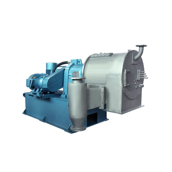
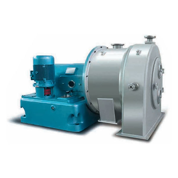
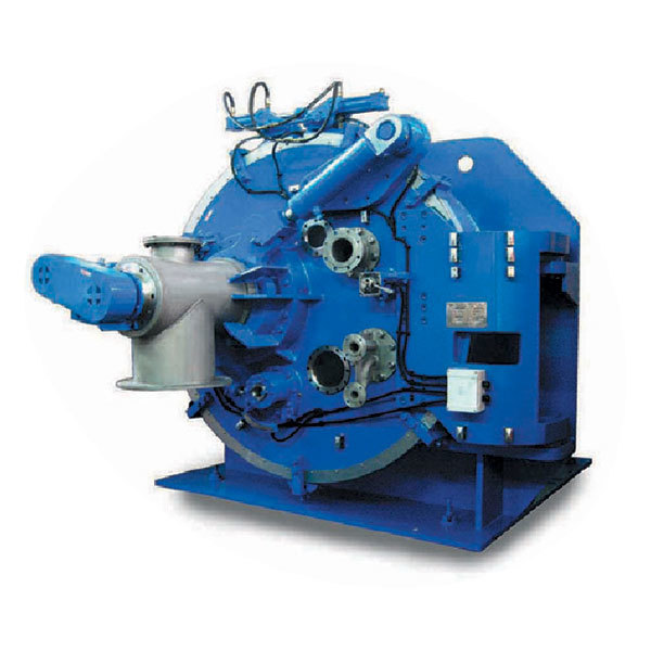
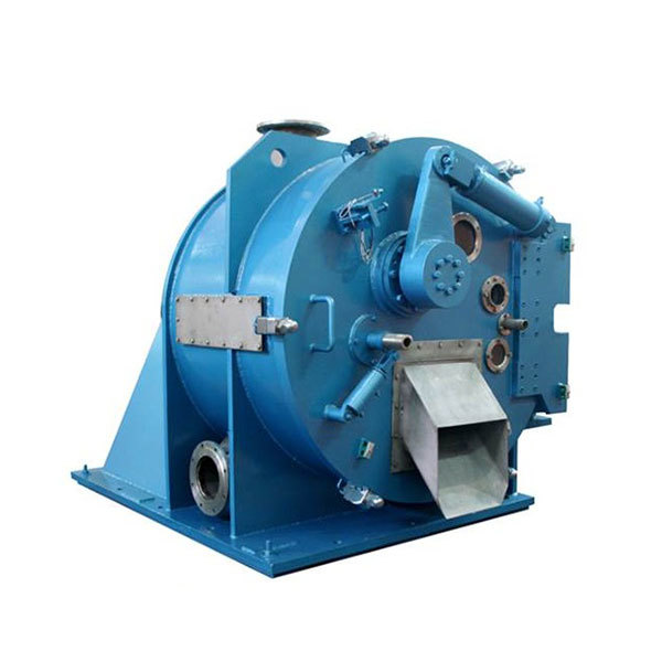
HR two-stage pusher centrifuges are supported on a frame through bearing assembly and mainly composed of oil pump assembly, pusher mechanism, frame, bearing assembly, basket, screen, and casing. For the 280/400/500 series, an oil cooler is installed inside the oil tank of the frame and the pump assembly is supported by the frame, with the oil pump inserted into the oil tank. For the 630/800/1000 series, an external oil cooler is used. The rotating assembly is connected to the rotor motor pulley through V-belts. The electric control box is a separate system, and the electric control cabinet is installed in the electric control room. The on-site operation box is installed in a suitable position near the centrifuge.
Special design features
The entire operation process is fully automatic and runs continuously without manual intervention. The machine is able to complete feeding, filtration, washing, dewatering, discharging and other steps at full speed, and suitable for the separation of concentrated suspensions containing crystal or short fibrous particles (solid content 30% -90%), with low particle breakage, filter cake washing available, large capacity, high solids recovery, low filter cake moisture, and low energy consumption. The technical parameters can be optimized for specific situations to better meet the needs of customers. The stroke frequency can be adjusted to better adapt to process changes. Pipe feeding or screw feeding can be selected for a wider range of applications according to different suspensions.
Applications
The centrifuge is suitable for separating suspensions containing crystal or short fibrous particles with good filtration properties. The average particle size of the solids is 0.08-3mm, with a concentration (volume ratio) of 30-80%, such as anilino acetonitrile, acrylamide, nickel acetate, acetate fiber, sodium dichromate, soda ash, succinic acid, paraxylene, wastewater salts, ammonium perchlorate, phosphate, sulfate, nitrate, ammonium chloride, potassium chloride, lithium chloride, ferrous chloride, potassium chlorate, chloroacetic acid, cotton seed, gelatin, urea, boric acid, lithium hydroxide, potassium carbonate, ammonium bicarbonate, potassium bicarbonate, urotropine, nitrocellulose, magnesium sulfite, sodium sulfite, sodium nitrite, aluminum oxide, and heavy alkali (secondary dewatering).
HR two-stage pusher centrifuge Standard Sizes and Technical Data
| specifications | Basket diameter(mm) | Filter length(mm) | Speed(r/min) | Separation factor(Fr) | Push stroke(mm) | Push frequency(min-1) | Main motor power(kW) | Oil pump motor power(kW) | Capacity (t/h) (under optimal conditions) | Weight of host(kg) | Dimension(mm) |
|---|---|---|---|---|---|---|---|---|---|---|---|
| HR280-N | 230/280 | 120/120 | 1800-2800 | 507-1228 | 40 | 30-80 | 5.5-11 | 4-5.5 | 0.5-1 (ammonium sulfate) |
1875 | 2210×1460×1095 |
| HR400-NA | 337/400 | 160/160 | 1400-2300 | 400-1180 | 40 | 30-80 | 7.5-15 | 5.5-7.5 | 2-2.5 (ammonium sulfate) |
1945 | 2530×1290×1155 |
| HR420-NB | 357/420 | 160/160 | 1400-2300 | 426-1243 | 40 | 30-80 | 15 | 5.5-7.5 | 2-2.5 (ammonium sulfates in flue gas) |
1960 | 2530×1290×1155 |
| HR500-NA | 410/500 | 180/180 | 1200-2000 | 400-1120 | 50 | 50-75 | 37-55 | 22 | 12-18 (salt) |
3357 | 3710×1380×1750 |
| HR630-NB | 560/630 | 240/240 | 1000-1800 | 350-1140 | 50 | 30-80 | 45-75 | 30 | ≥25 (salt) |
3950 | 3115×1500×1360 |
| HR800-NA | 720/800 | 300/300 | 800-1600 | 290-1150 | 50 | 30-80 | 55-90 | 45 | ≥40 (salt) |
6000 | 3650×1880×1610 |
| HR1000-NA | 918/1000 | 330/330 | 850-950 | 405-505 | 65-75 | 30-80 | 90-110 | 55 | ≥28 (ammonium chloride) |
13000 | 3840×2150×1977 |
Pusher discharge
Filter
Screen
Recommended Products
Product Inquiry
Please make sure to fill in the information accurately and keep your communication channels open. We will contact you as soon as possible


